Setting the standard. Sharing the system. Signature is our digital resource for restaurant booth CNC files and frame plans: identifiable parts, explicit dimensions, documented builds and a repeatable workshop handoff. We’re opening our system so other builders can work from the same foundation.
DESIGNED BY US BOOTHSSignature collection reference
Signature / Source model documentation
Two original designs. One documented foundation.
Explore the existing US Booths straight and curved corner models, recovered from the original SketchUp-to-GLB workflow. Inspect the full structure and review the generated pieces below. Dimensions describe bare structural components, before upholstery.
Measurement status
The original component catalogs record millimeters and inch reference dimensions. This page displays inches. X/Y/Z are the GLB source axes; Y is vertical. The shared library below numbers each unique profile once and lists its quantity in each model.
SIG-ST / Source review
Straight module
A linear seating frame with a rectangular seat deck, lower plinth, upright back supports and longitudinal rails. Designed as the straight component of the Signature seating family.
X span / depth
25.25 in
Y span / height
42 in
Z span / length
47.5 in
Source assembly members
33
Download this model’s component set. Shared component IDs and quantities are listed in the library below.
Loading original 3D model…Click a piece to find its component · Drag to orbit · Scroll or pinch to zoom
SIG-CR / Source review
Curved corner module
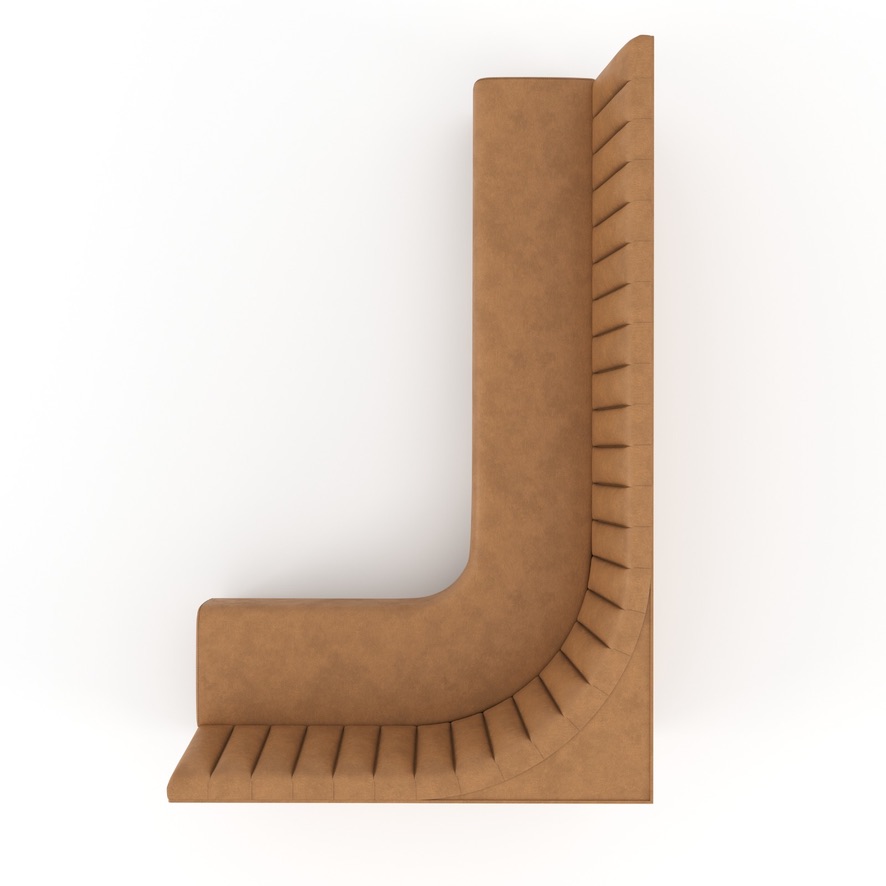
A corner seating frame with a curved seat deck and back support geometry. The supplied model occupies a square envelope and connects two seating directions; its contours must be retained when preparing the parts.
X span / depth
47.5 in
Y span / height
42 in
Z span / length
47.5 in
Source assembly members
52
Download this model’s component set. Shared component IDs and quantities are listed in the library below.
Loading original 3D model…Click a piece to find its component · Drag to orbit · Scroll or pinch to zoom
US Booths | Signature / Component system
Unique components. Designed to be reused.
One numbered component per matching profile, with no duplicate cards. Contours, holes and stock thickness define a component; quantities show how each design uses it.
Preparing the shared component library…
The same component ID is used in both DXF archives. Each model’s quantity schedule includes its required quantities and the original Frame Builder source IDs.
US Booths | Signature / Manufacturing guide
The Signature standard. From design to production.
Our manufacturing standard connects the straight and curved Signature designs to a documented workshop process. Follow the same framework through preparation, machining, assembly and upholstery. The source models are available to inspect; material, joint and finished upholstery specifications still need to be recorded for the released build.
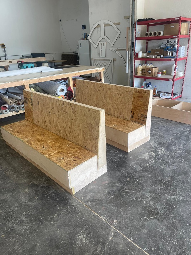
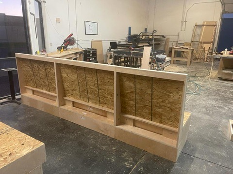
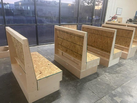
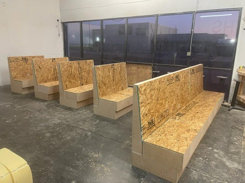
Photographs show real workshop builds and finish variations supplied by US Booths. They illustrate the process; they are not a single before-and-after sequence or verification of a specific CAD revision.
Stage 01 / Signature
Define the seating project.
Start with the room and the finished seating requirements. The structure is one part of the project; the upholstered dimensions must also fit the space.
Record the available wall lengths, corners, access route and connection points between modules.
Choose the straight module, curved corner module or a combination of both. Identify each module on the layout.
Record the intended finished seat height, overall back height, upholstery style and material selection. Keep those finished dimensions separate from the bare-frame dimensions.
Stage handoff
A dimensioned layout and a written finish specification.
Stage 02 / Signature
Review the standard model in 3D.
Use the original Signature model as the common reference for the workshop. Frame Studio opens with the selected structure already loaded.
Open the model, orbit the assembly and inspect the base, seat deck, supports, braces and back cover.
Review the shared component library and the selected model’s quantities. Its SC IDs map to the original Frame Builder source IDs in the downloaded schedule; open Frame Studio for individual 3D inspection.
Record changes as a new revision. Do not mix dimensions from an altered model with files from the original release.
Stage handoff
One identified model revision, with every change recorded.
Stage 03 / Signature
Prepare the material and hardware schedule.
A geometry file defines shape. The shop specification defines what the shape is made from and how it is joined.
Record the sheet material and actual measured thickness for each part family. Compare it with the modeled stock thickness.
Specify the fasteners, adhesive, pilot holes and joint details used by your approved shop build. Those details are not supplied by a bounding-box table.
List foam, batting, upholstery, backing and finish materials separately. Record the supplier references and intended quantities.
Stage handoff
A material schedule and an approved joint specification.
Stage 04 / Signature
Prepare profiles, then machining.
Each model downloads its own archive of generated DXF profiles in millimeters. A DXF contour is a source for CAM; it is not a machine program.
Download the straight or corner DXF archive and locate the required part ID. Confirm the imported scale against the displayed dimensions; the files declare millimeters.
Review the outer contour and internal holes. For curved, bent or inclined parts, prepare a developed profile in Frame Studio rather than treating the exterior envelope as a flat pattern.
Prepare the sheet layout, cutter compensation, toolpaths and workholding in your CAM workflow. Confirm the setup on the actual machine before producing a batch.
Stage handoff
Reviewed profiles and a machine-specific machining setup.
Stage 05 / Signature
Cut, label and inspect every part.
Carry the component ID from the digital catalog onto the physical piece. Identification is what keeps a repeatable model repeatable on the shop floor.
Keep the component ID and revision attached to the part through cutting and assembly. Separate straight and corner sets.
Inspect the cut outline, holes and mating edges against the reviewed profile. Record parts that need rework before assembly.
Count the components against the catalog. Sort them into base, seat, back and brace groups.
Stage handoff
An identified and inspected set of physical components.
Stage 06 / Signature
Dry-fit the lower base.
Start with the lower structural group and its braces. Work from the assembly geometry, not from the perspective view alone.
Locate the base front, base sides, interior braces and triangular braces in the 3D assembly. Use the downloaded schedule to map each shared component ID to its original Frame Builder source code.
Dry-fit the members in their modeled positions. Check the overall footprint and the meeting surfaces before applying the approved fastening method.
For the corner, review both seating directions and the extension components. Verify the complete footprint with the curved structure in place.
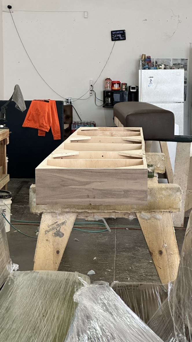
Workshop example: the open base shows crossmembers and triangular braces before the seat deck is fitted.
Stage handoff
A checked lower base, ready for the approved joining sequence.
Stage 07 / Signature
Fit the seat and back structure.
The straight module and curved corner share a fabrication language, while their seat and back profiles differ.
For the straight module, locate the seat supports and deck, then the back uprights, mounting supports, rails and cover.
For the corner, inspect the curved seat supports, bottom and deck, followed by the curved back members and cover. Preserve the source contours and orientation.
Dry-fit the complete structure. Resolve interference, connection access and any changed joint dimensions before final fastening.
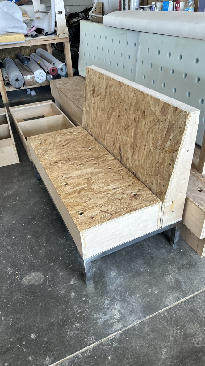
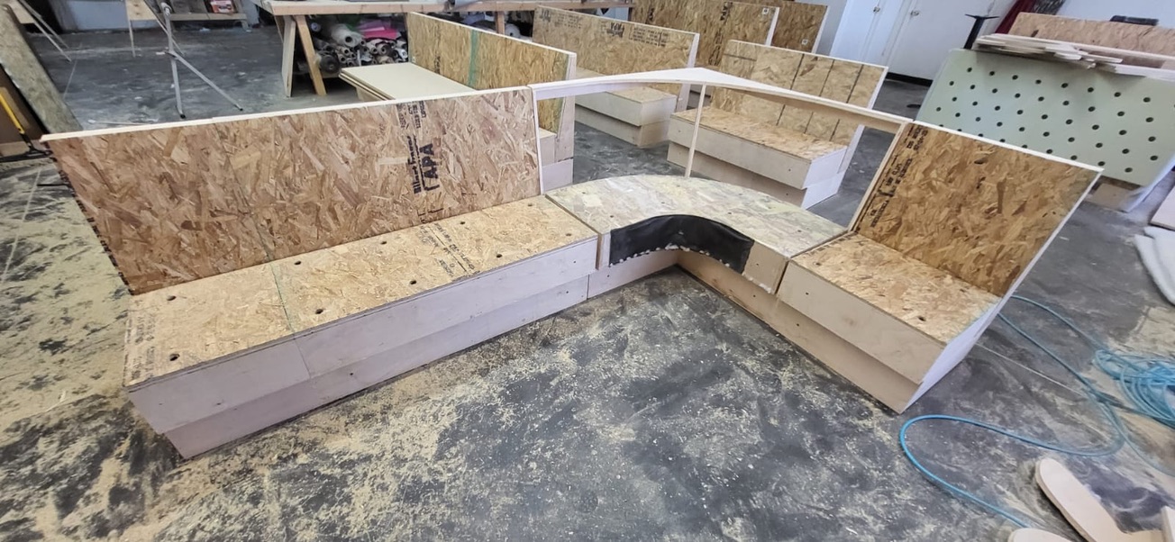
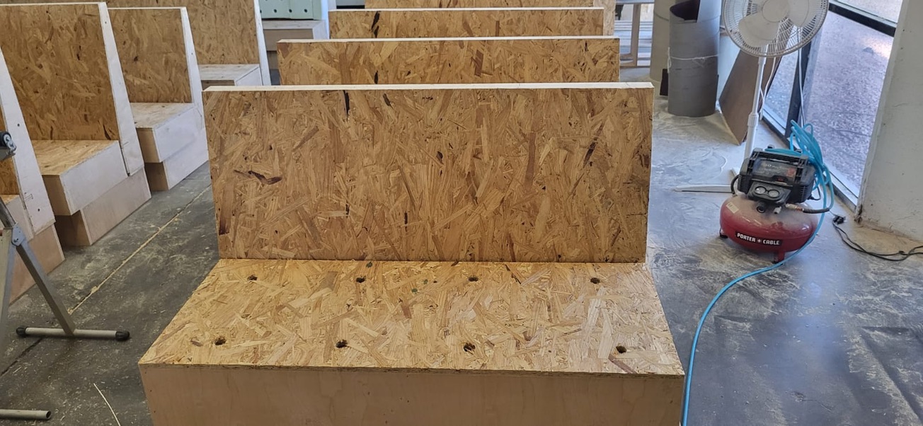
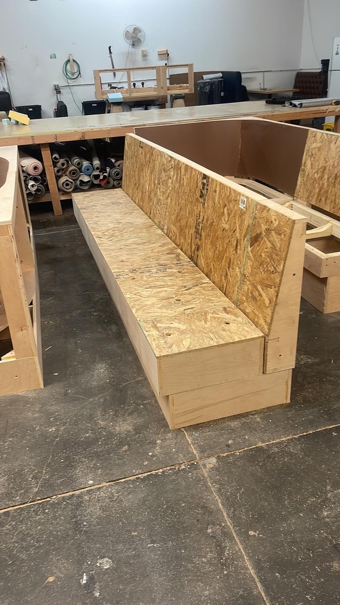
Straight frame example: seat deck, back panel and perimeter members remain visible before upholstery.Corner layout example: straight members and the curved transition are reviewed together before covering.
Stage handoff
A complete bare frame checked against the selected revision.
Stage 08 / Signature
Prepare and apply the upholstery.
Use the selected finish specification to turn the frame into the finished seating design. Upholstery adds dimensions beyond the structural model.
Prepare the surfaces and backing required by the approved upholstery method. Inspect areas that will become inaccessible after covering.
Apply the specified foam, batting and upholstery pattern. Keep reference points consistent between adjacent straight and corner modules.
Check the finished seat height, depth, back profile, seam alignment and module connection. Record the actual finished dimensions.
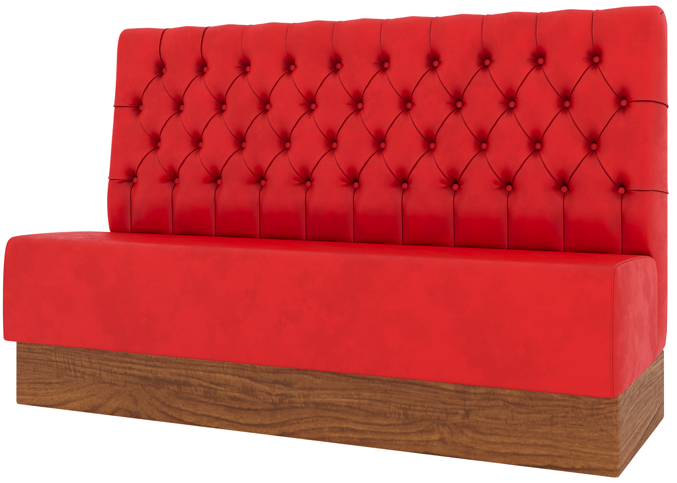
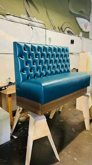
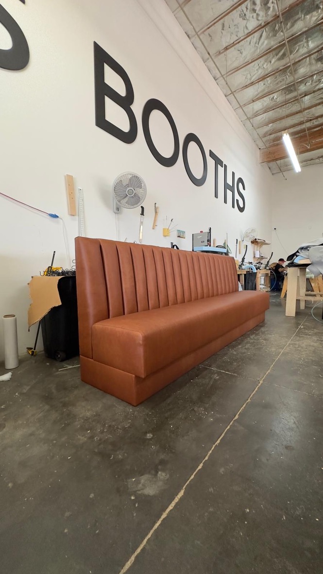
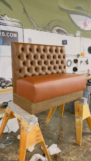
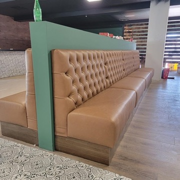
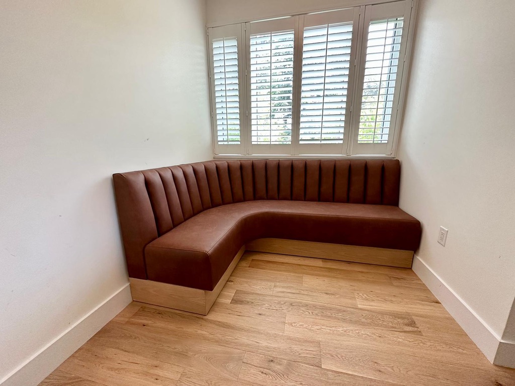
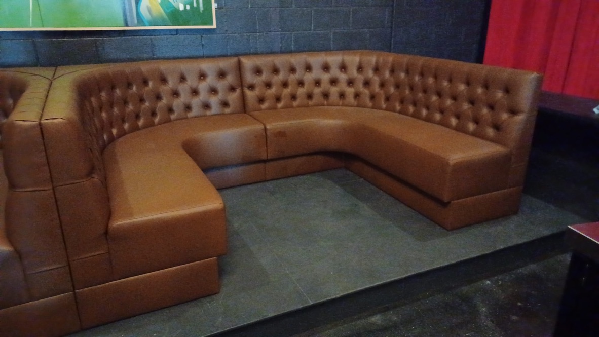
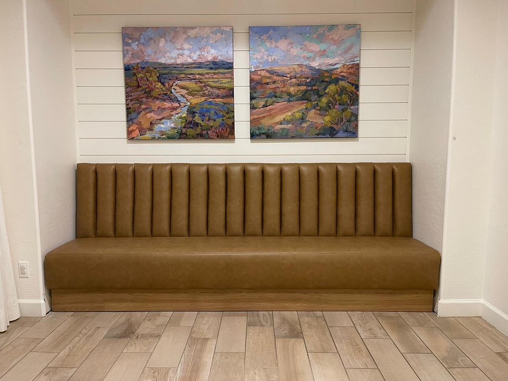
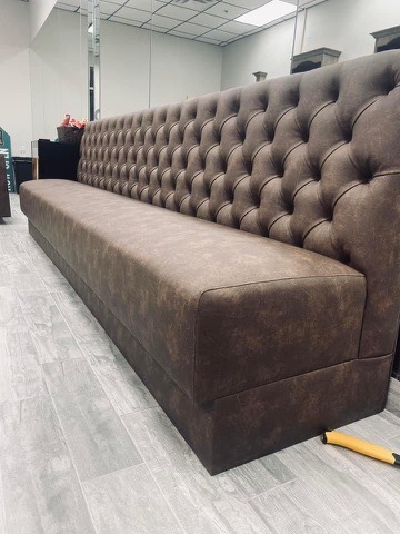
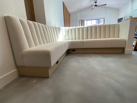
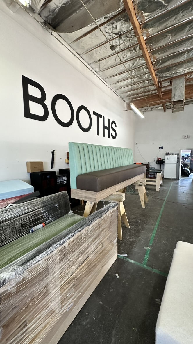
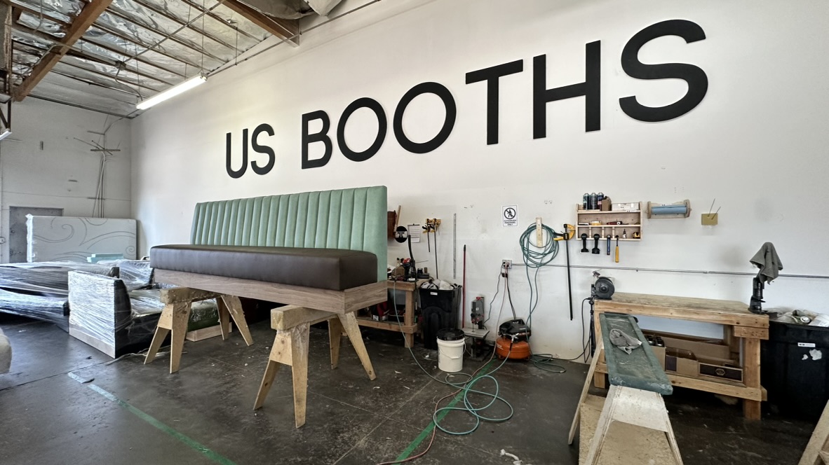
Finished upholstery example: diamond tufting with a smooth seat and exposed base finish.Finish variation: vertical channels create a different upholstered expression.
Stage handoff
A finished module with its upholstery specification and dimensions recorded.
Stage 09 / Signature
Review the complete build.
A finished appearance alone does not complete the manufacturing record. Inspect the structure and the assembled seating before accepting the build.
Review joints, fasteners, access points and component fit using the approved shop acceptance criteria.
Check the finished dimensions, edges, upholstery alignment and fit between modules against the project brief.
Resolve issues on the physical prototype before repeating the build. Record what changed in the drawings, profile files or material schedule.
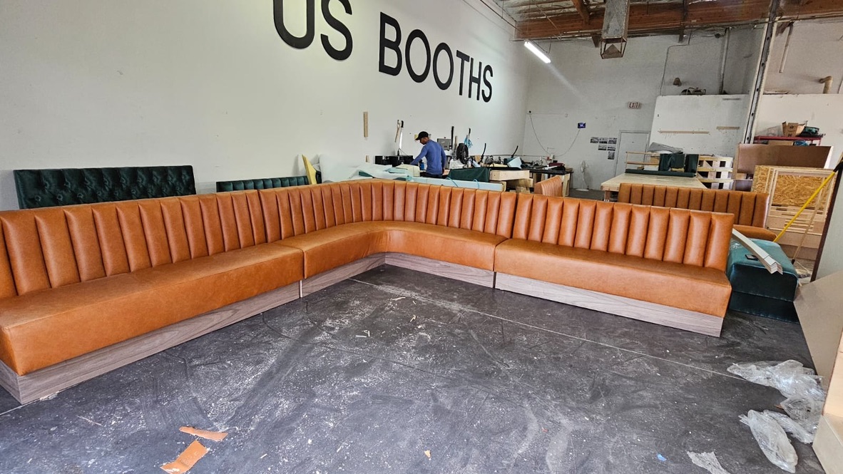
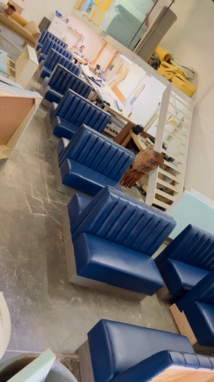
Workshop layout review: adjoining seat sections, channel alignment and the corner transition can be viewed together.
Stage handoff
An accepted prototype and a documented list of resolved changes.
Stage 10 / Signature
Package a repeatable manufacturing record.
The asset is the complete handoff: a design another builder can identify, review and reproduce.
Keep the model, component catalog, reviewed profiles, material schedule and assembly instructions under one revision.
Include the prototype review and actual finished dimensions. Identify machine-specific CAM files separately from design source files.
Publish the contents and permitted uses clearly. The complete $399 CNC package remains in preparation until its specification and release terms are finalized.
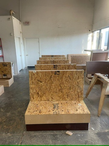
Repeated builds: multiple frames staged for the next workshop operation.
Stage handoff
A traceable design-to-workshop package.
The production record
A model becomes repeatable when the handoff is complete.
Use the same record for the first prototype and each subsequent revision. It connects the digital design to the physical build.
Record
What it must identify
Current source status
Design source
Model, module and revision
Straight and corner GLB models available
Component catalog
Part IDs, quantities and reference dimensions
Shared component library and per-model quantities available
Flat profiles
Contour, holes, units and part ID
Separate straight and corner DXF archives available
Curved profiles
Developed shape and assembly relationship
Development and review required
Materials & joints
Stock, measured thickness, hardware and adhesive
Release specification to be completed
Upholstery
Foam, covering, pattern and finished dimensions
Release specification to be completed
Build acceptance
Physical prototype review and resolved changes
Review record to be attached
US Booths | Signature — Designed, built and documented.
We create the design. We define the method. We share the standard.
Signature is our answer to how booth manufacturing should be documented and repeated. The standard connects the design, named components, dimensions, materials and production records into one manufacturing language.
Our ambition is to make that language a reference across the industry. Open Design lets other builders study the system, adapt it and contribute to its development.
The Signature model / 02
Different spaces. A shared foundation.
Custom dimensions and finishes define the project. A repeatable approach connects the design to the workshop.
01 / DEFINE
Design intent.
Start with the space, seating layout, dimensions and material choices.
02 / STRUCTURE
Build logic.
Connect the visible design to the parts and relationships that support the build.
03 / DOCUMENT
A common language.
Make dimensions, materials, revisions and assembly information explicit.
04 / PRODUCE
Repeat the process.
Translate a documented design into workshop preparation and CNC files.
SIGNATURE / DESIGN → STRUCTURE → DOCUMENTATION → PRODUCTIONConceptual system diagram · Not a cutting plan
Our open design principles / 03
Define the standard. Make it transferable.
These are the principles of the Signature manufacturing standard. They define what we expect from a transferable design and guide the first open release.
01
Share the source.
Publish editable design files alongside the documentation. A picture can inspire a build; source files let a builder work with the design.
02
Define the permission.
Make the license and rights to use, modify, manufacture and redistribute visible with the release.
03
Make revisions traceable.
Identify the released model, version and file contents so builders know exactly which design they are working from.
04
Document the handoff.
List formats, dimensions, material assumptions and assembly information before a builder downloads or buys files.
US Booths | Signature / Workshop & finish references
The structure behind it. The possibilities around it.
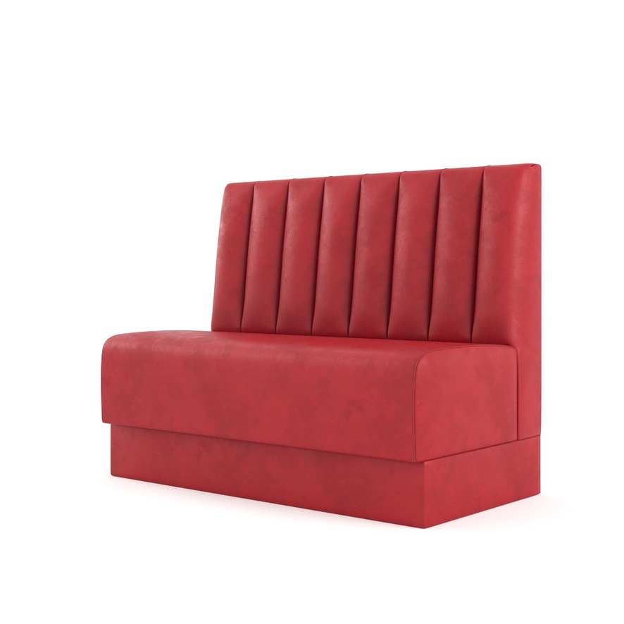
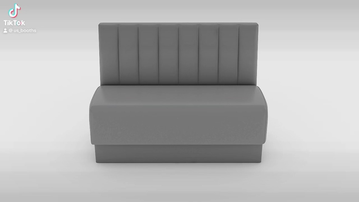
Additional construction views, upholstery treatments and installed seating from the supplied collection. Product renders are labeled separately. Each example illustrates a finish or configuration; it does not establish the dimensions of the released CAD model.
US Booths | Signature / Digital manufacturing resource
Restaurant booth CNC files. Built around an actual frame system.
US Booths | Signature brings restaurant booth frame plans, 3D component inspection and downloadable DXF profiles into one documented manufacturing resource. Choose a straight booth or curved corner structure, review the pieces and carry their IDs and quantities into your workshop.
For furniture makers, upholstery shops and commercial seating fabricators across the United States, the starting point is the same: an identifiable design, a matching set of parts and a clear fabrication record. Our goal is to establish a shared manufacturing standard that other builders can work from.
01 / Straight booth frame plans
A repeatable linear module.
Inspect the straight seating structure in 3D and download its own DXF archive. The schedule identifies the generated profiles and quantities for the base, seat, back supports and braces.
Review the corner structure and its curved seat and back components. Its archive is separate from the straight model; profiles marked for review require development or confirmation before machining.
The downloaded outlines preserve the generated outer contours and holes. Bring the files into CAD/CAM, verify millimeter scale and prepare a cutting setup for your selected stock and machine. Then follow the Signature guide through part identification, frame assembly, upholstery and physical prototype review.
A floor-plan CAD block shows where seating goes. This resource focuses on the structural pieces that make the seating buildable. It does not replace a material schedule, assembly specification or machine-specific CAM review.
They are digital part profiles used to prepare the structural components of restaurant booth seating for fabrication. Signature provides DXF profiles generated from its straight and curved corner frame models, with component IDs, reference dimensions and quantities.
What is included in the DXF download?
Each model has its own ZIP: one for the straight booth frame and one for the curved corner. Each ZIP contains generated DXF profiles, a parts.csv quantity schedule and a README. Profiles requiring additional review are placed in a review-required folder.
Are the DXF files in inches or millimeters?
DXF geometry is exported in millimeters and declares that unit in its header. The page and quantity schedule show reference dimensions in inches. Check the imported scale before preparing toolpaths.
Can I use these files with a CNC router?
Use the DXF outlines as input to your CAD/CAM workflow. Review contours, stock thickness, cutter compensation, workholding and your machine setup. The download contains design profiles; it does not include machine-specific G-code or an approved cutting setup.
Do the plans include upholstery instructions?
The manufacturing guide covers the workflow from frame preparation to upholstery and final review. Foam, covering, fasteners, adhesive and finished upholstery dimensions still need to be specified for the released build.
Can I customize the restaurant booth frame?
Open the standard model in Frame Studio to inspect and edit the structure. After a design change, regenerate and review the matching part profiles rather than reusing files from the original revision.
Can builders across the United States use this resource?
This is a digital design resource for furniture makers, upholstery workshops and commercial seating fabricators across the United States. The files are downloaded online. Manufacturing, materials and installation are handled through your own reviewed workshop process.
What is the $399 CNC package?
The complete Signature CNC package is a planned digital offer priced at $399 USD. Its final contents and release terms are being prepared. The current model downloads are generated reference profiles; purchasing the complete package is not yet active.
Restaurant furniture / Dimension planning
Common dimensions. Clear design decisions.
These are common U.S. planning references, not a single mandatory size for all restaurant furniture. Finished upholstery dimensions, frame dimensions and accessibility requirements describe different things.
What is a typical restaurant booth seat height?
Around 18 inches from the floor to the finished seat. Measure the upholstered seat, not the bare deck.
How high is a standard restaurant dining table?
About 30 inches is a common dining-table reference, typically paired with an approximately 18-inch seat.
What is the usual booth seat depth?
A usable seat depth of 16–18 inches is common. Overall booth depth also includes the back structure and upholstery.
How much seating length should I allow per guest?
About 24 inches per guest is a common planning reference. A 48-inch bench is often used for two guests on one side.
What dimensions are common for bar-height seating?
A seat around 30 inches high commonly pairs with a 42-inch table. These are different from standard dining-height frames.
Is 42 inches a standard booth back height?
42 inches is a commonly offered overall booth height. Other heights suit different layouts; the finished build and sightlines determine the selection.
What are the ADA height requirements for an accessible dining surface?
For adult use, ADA section 902.3 specifies a tabletop 28–34 inches above the finished floor. Section 902.2 also requires a forward approach and compliant knee and toe clearance. Table height alone does not establish accessibility.
How wide must an accessible circulation route be?
ADA section 403.5.1 generally requires 36 inches of clear width. Limited reductions, turns and passing spaces have separate provisions. Assess the complete route and applicable project requirements; 36 inches is not a universal specification for every restaurant aisle.
The shown Signature structures are bare-frame models. Their 42-inch nominal overall height is not a seat-height specification. The seat deck, foam and upholstery must be considered together to establish the finished seating dimensions. Review the selected model and finish schedule before changing any CNC profile.